


Shanghai Richtech Engineering Co., Ltd.
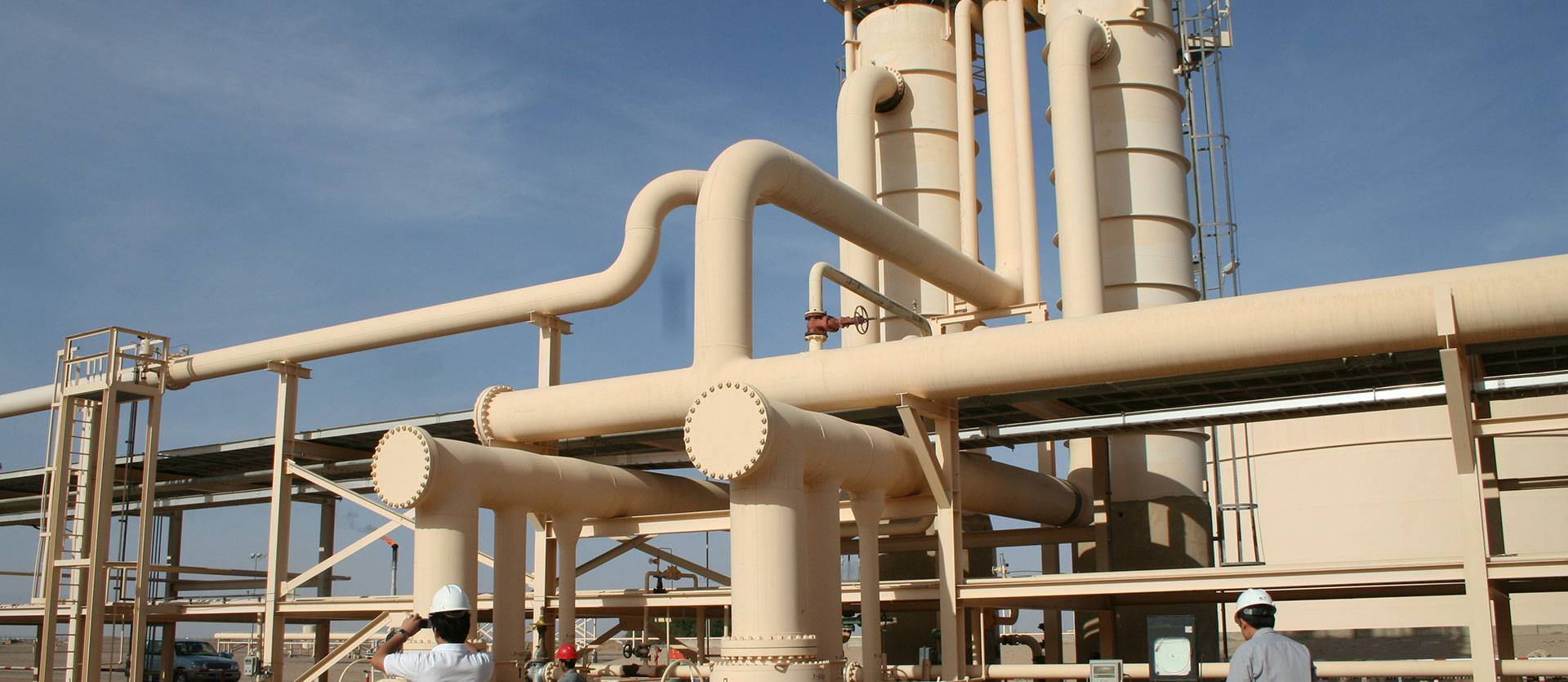
Shanghai RICHTECH Engineering Co., Ltd. (Stock Code: 832547; “RICHTECH” for short) is an international engineering service company featured by diversified business models and engaged in clean energy and marine economy at the middle and upper streams of energy industry and a pioneer in strategic emerging industries of China.
Founded in 2003
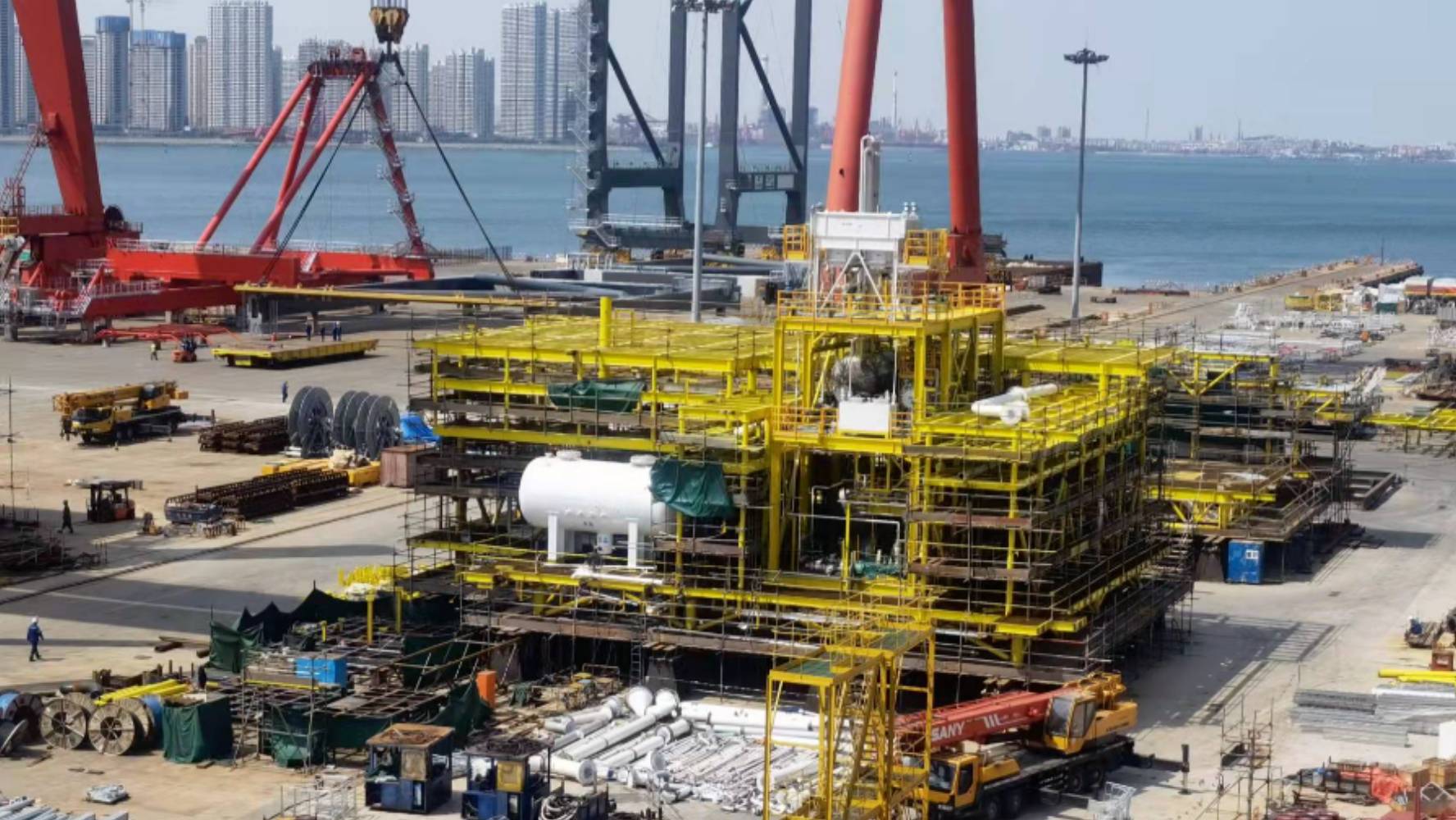
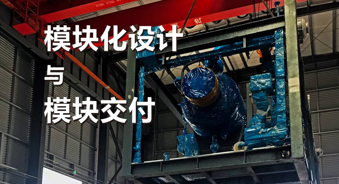
RICHTECH, founded in Houston in 2003, the USA, based in Shanghai, China, has branches in Beijing, Tianjin, Shenzhen and Chengdu and has wholly-owned subsidiaries in counties and regions including the USA, Singapore, Burma and Hongkong. In the past decade, the Company, by virtue of reliable engineering capacity and rich experiences in engineering projects, has provided global energy firms, oil and gas operators and engineering companies at home and abroad with engineering consultation, engineering design, project management, procurement management, EPCM and modular EPC services in the fields of oil and gas as well as marine engineering. The business of the Company covers China, Southeast Asia, Middle East, West Africa, Australia, Gulf of Mexico, Russia, etc.
Value Proposition
Responsibility Communication ProgressVision
Low-carbon & smart technology for global energy industryMission
Sustainable innovation,Valuable engineering solution